Application noteInspecting solder joints and components on PCBs
The short answer
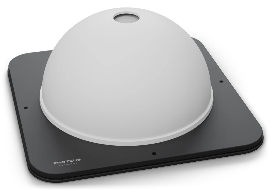
Use a dome light. A good solder fillet is curved and shiny, and under a dome it shows as a smooth, bright band. Starved joints, bridges and missing parts change that shape, so they stand out.
- Technique
- Dome
- Industry
- Electronics
What the camera sees
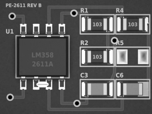
Camera views are simulated: the part and the lights are modelled, then rendered as a monochrome camera would see them.
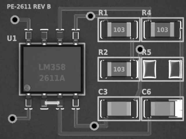 Ring lightDome
The problem
After reflow, every joint has to be wetted and properly shaped, every component has to be there, and no solder may bridge two leads. Solder is a curved mirror. Under a ring light it reflects the LEDs as thin glints wherever the surface happens to face them, so a good joint and a bad one both look like dark shapes with a few bright lines. Component bodies, silkscreen and the glossy board add reflections of their own.
Why it works
A dome surrounds the board with light from every direction. A well-wetted fillet slopes from the component down to the pad, and whatever its angle, it reflects some part of the dome into the lens: it shows as a smooth, bright band. A starved joint is nearly flat, so it reflects the camera hole at the top of the dome and stays grey. A bridge shows as a bright blob joining two leads, and a missing part leaves two bare pads. Markings on the component bodies read evenly, without hot spots.
How to set it up
- Choose a dome that covers the whole field of view, with the board close enough to sit inside its even light.
- Expect the flat tops of pads and components to look darker: they reflect the camera hole. That helps, because flat solder is the defect.
- For markings and polarity marks on flat, glossy parts, a co-axial light gives the most even background.
- A colour camera with a white dome shows component colours and discoloured boards; a monochrome camera with red light gives the sharpest contrast on solder.
- Fix the board height. A board that sags or sits off-centre takes its edges out of the even light.
What usually goes wrong
- A ring light at the lens, which turns every joint into a few bright glints.
- A dome too small for the board, so components near the edges fall outside the even light.
- Expecting one top-down image to judge joint height. Lifted leads and tall joints need an angled view or a 3D measurement.
Lights for this job
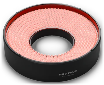
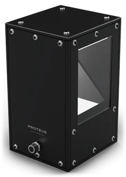
More application notes
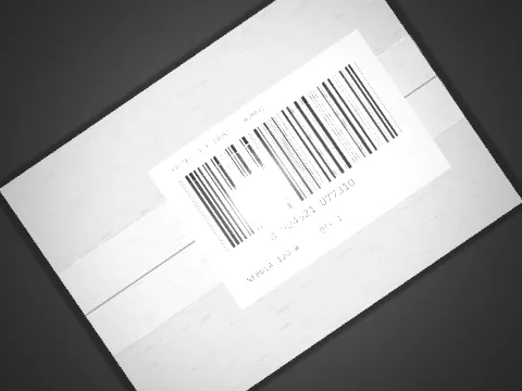
Bright field, red
Using coloured light to hide or highlight printLight the part in the same colour as the print you want to hide, or in the opposite colour to make it stand out.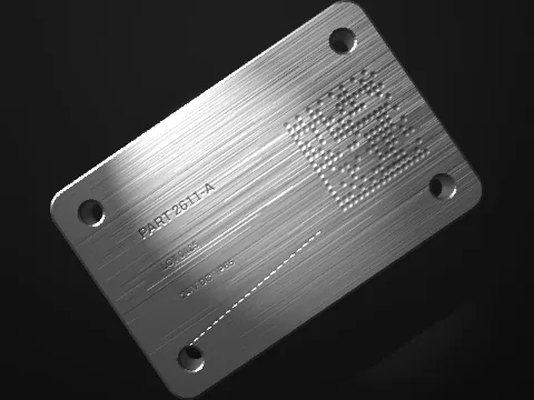
Spot
Picking out one feature with a spot lightUse a focused spot light.
Co-axial
Reading laser marks on flat metal and plastic partsUse a co-axial light on smooth, flat faces.
Tell us what you need to see.
Describe the part, the defect and the working distance. An engineer replies with the light, or designs one.