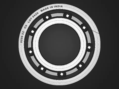
Why the light decides the result
An inspection works when the feature you care about is clearly brighter or darker than everything around it, and stays that way from part to part. That contrast is created by the light, before the image reaches the software. An algorithm can sharpen and threshold an image, but it cannot recover detail the sensor never received.
Good lighting makes the feature obvious, keeps it stable as parts and positions vary, and lets you use simpler, faster software. Most failing vision systems are lighting problems first.
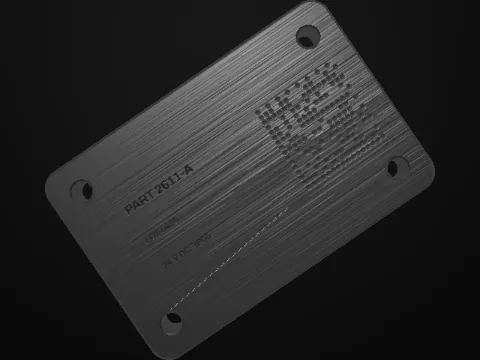
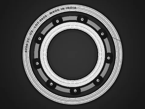
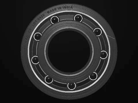
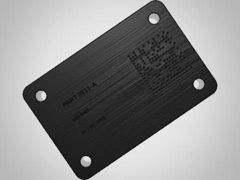 BacklightDark field
Start with the surface
Every lighting choice follows from how the surface returns light.
Matte surfaces such as paper, castings and most plastics scatter light in all directions. They look much the same from any angle and are forgiving to light.
Shiny surfaces such as polished metal, glass, film and glossy print reflect like a mirror. Light leaves at the same angle it arrives, so the camera sees a reflection of whatever the surface faces: a bright light, or a dark room.
Transparent and translucent parts let light through, which a backlight can use.
On shiny parts the key question is simple: should the reflection from the background go into the lens, or away from it?
That choice is the difference between bright field and dark field.
Bright field and dark field
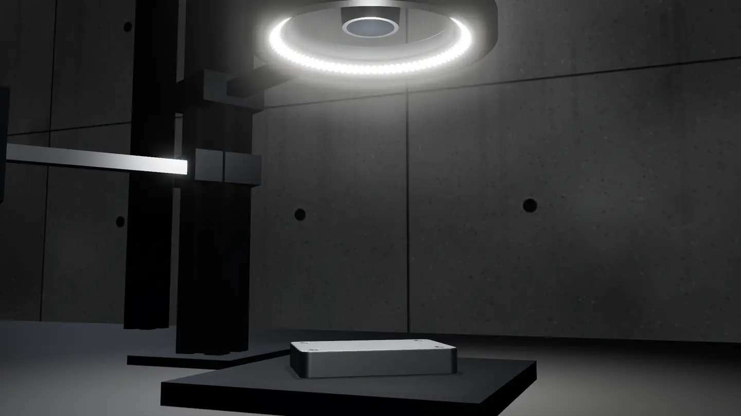
Bright field
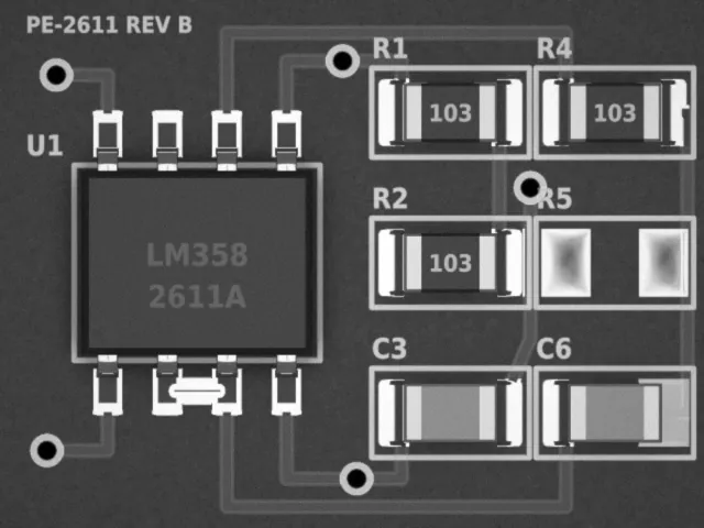
The light is placed so that a flat surface reflects it into the lens. The background is bright; marks, holes and anything that absorbs or scatters light look dark. A ring light near the lens and a co-axial light are bright-field lights.
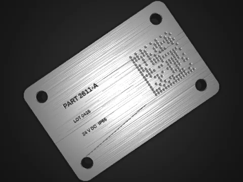
Dark field
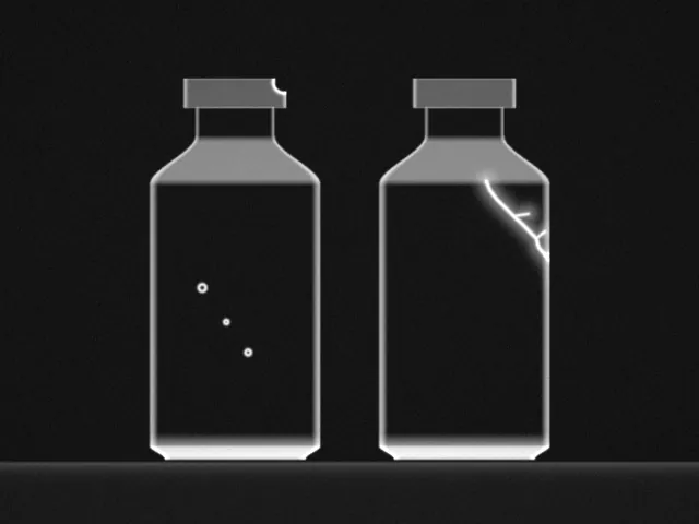
The light arrives at a low angle, so a flat surface reflects it away from the lens. The background is dark; edges, scratches, engraving, dust and anything raised or recessed catch the light and look bright. A low-angle ring light close to the part, or bar lights from the side, give dark field.
Most lighting problems on shiny parts are solved by choosing one or the other on purpose.
The eight lighting techniques
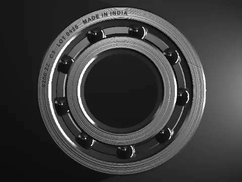
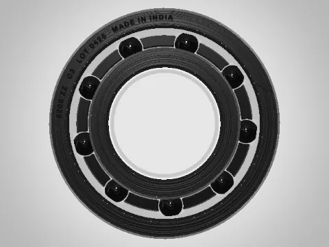
Each technique places the light differently relative to the part and the camera, and each answers a different kind of problem. Each picture shows the setup, with what the camera sees inset.
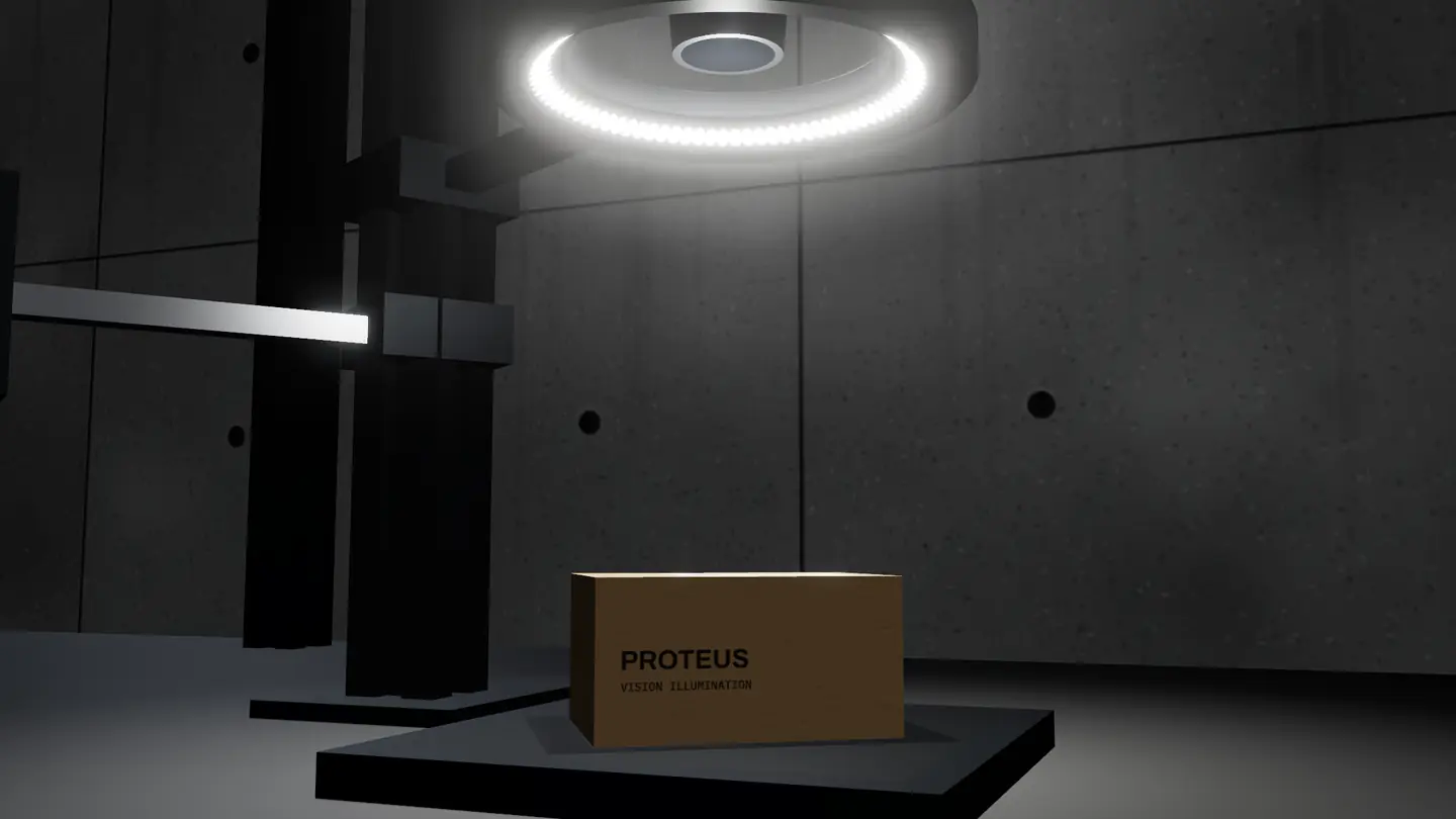
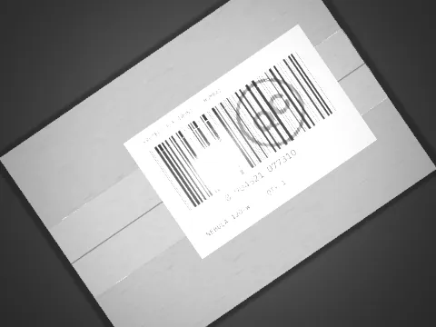
Ring light (bright field)
A ring of LEDs around the lens lights the part from above. Flat faces turn bright; print, engraving and stains turn dark.
Use it forCodes and print on labels, presence checks, general inspection of matte parts.
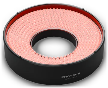 Saturn ring lights
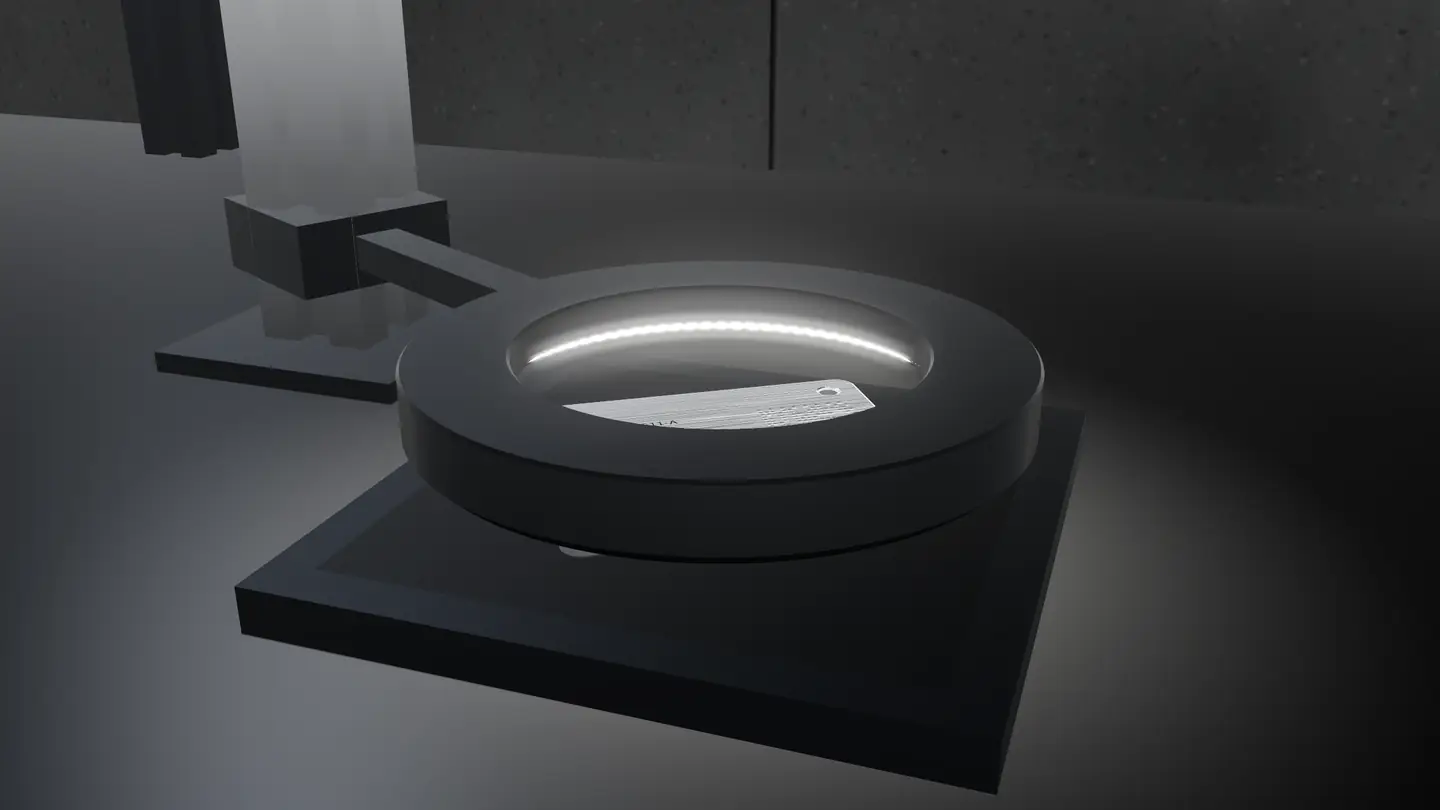
Low-angle ring light (dark field)
The same ring, placed close to the part so its light skims the surface. Flat faces go dark; edges, scratches and peened or engraved marks light up.
Use it forDot-peened codes, surface defects, edge detection on flat metal.
Saturn ring lights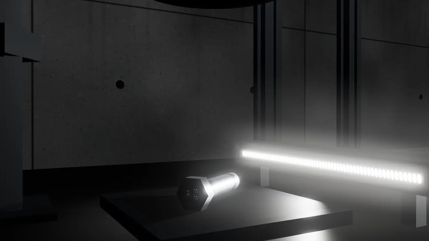
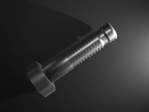
Bar light (directional)
One or more bars from the side. Relief and texture cast shadows, and reflections from glossy film are sent away from the lens.
Use it forTexture, embossing, threads, labels under film, line-scan cameras.
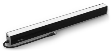 Comet bar lights
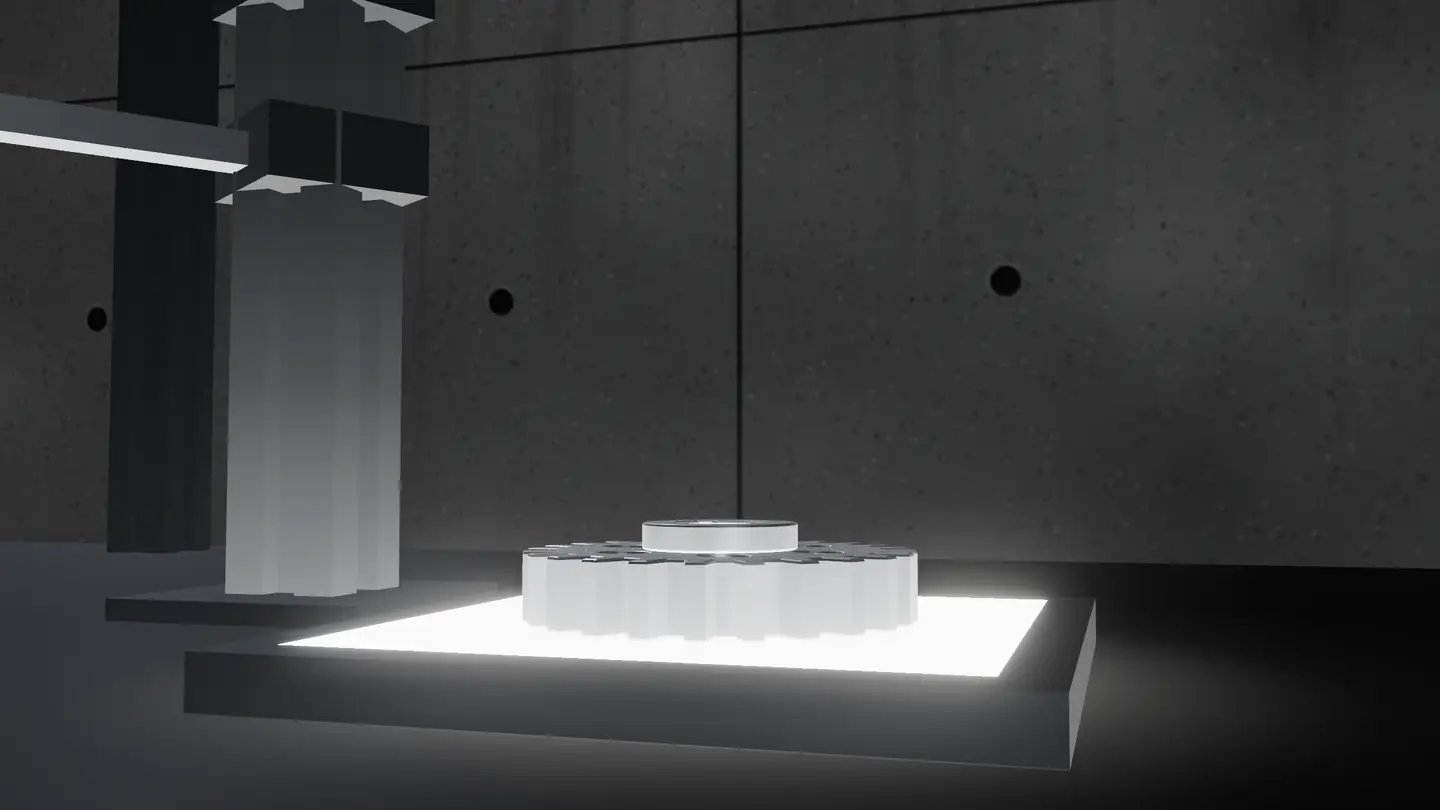
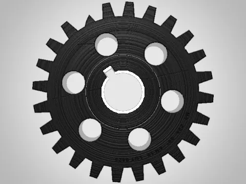
Backlight
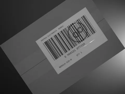
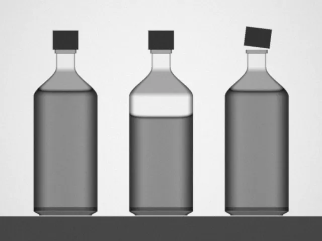
Light from behind turns the part into a silhouette. Surface finish stops mattering; only the outline remains.
Use it forMeasuring and gauging, thread and tooth profiles, holes, see-through parts.
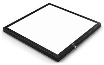 Nebula backlights
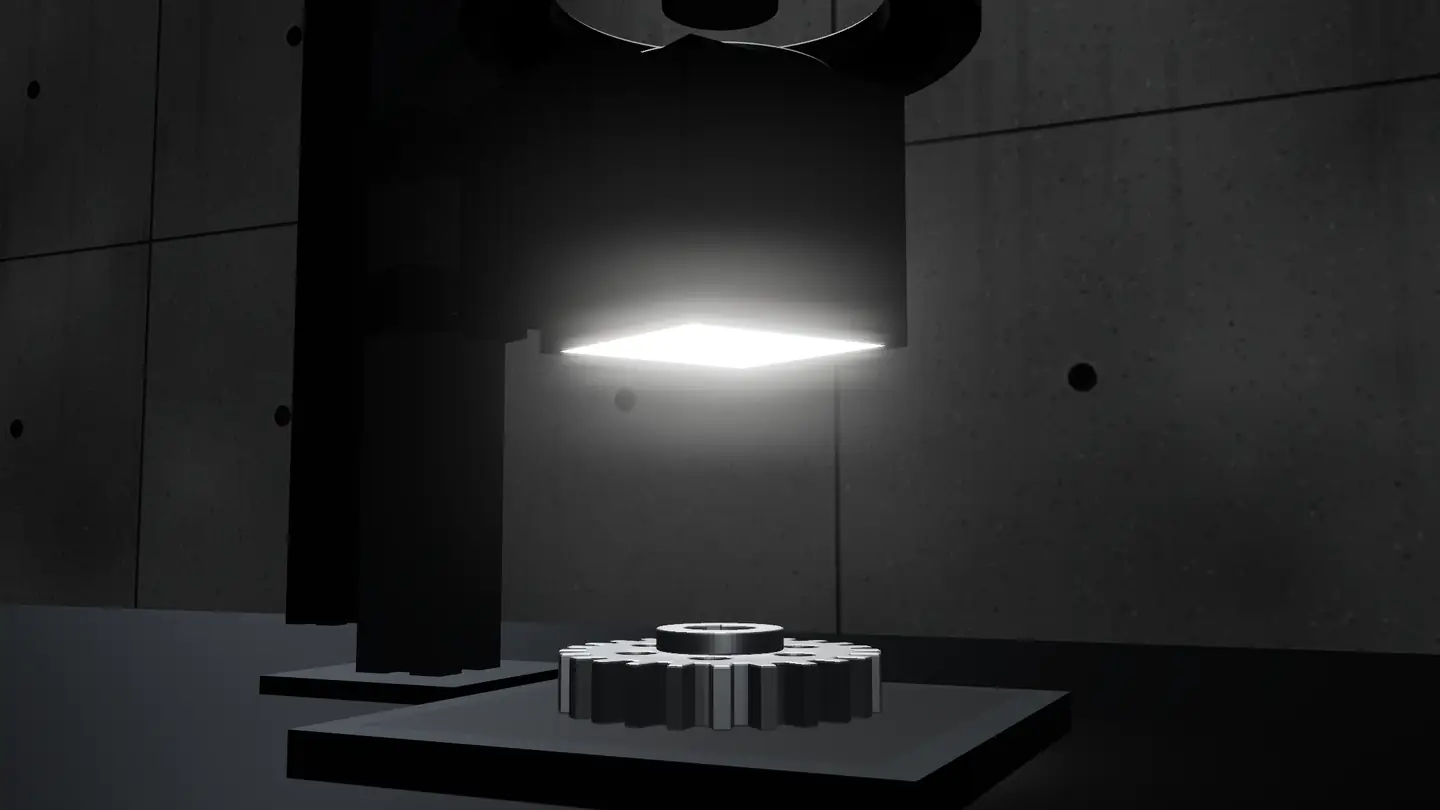
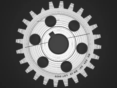
Co-axial light
Light travels down the camera's own axis through a beam splitter. Flat, mirror-like faces glow evenly; a scratch or dent breaks the reflection and shows dark.
Use it forFlat polished or ground faces, laser-etched marks.
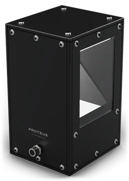 Quasar co-axial lights
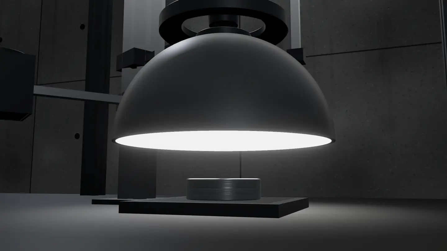
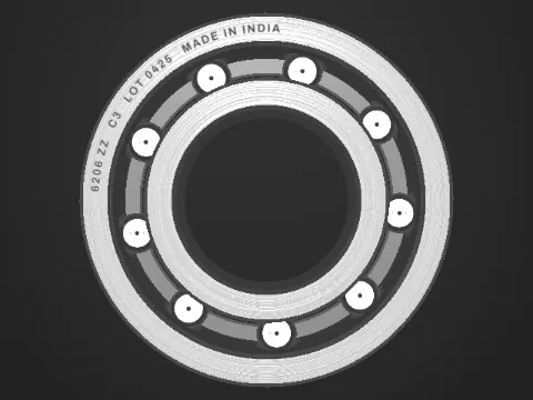
Dome light
Light arrives from every direction at once, from the inside of a white dome. Hot spots vanish on curved, shiny and uneven parts.
Use it forPrint and engraving on curved metal, foil packaging, electronics.
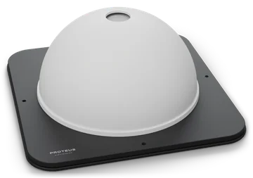 Aurora dome lights
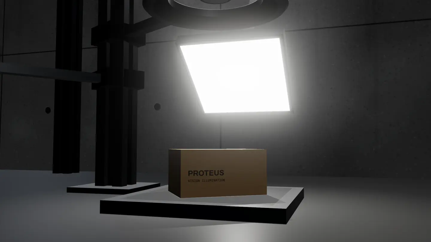
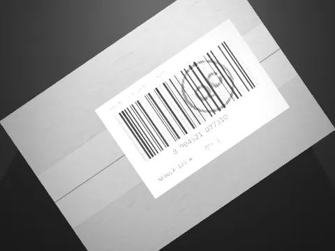
Area light
A broad panel covers a medium-to-large field of view evenly.
Use it forCartons, panels, trays, and reflective packaging such as foil and blister packs.
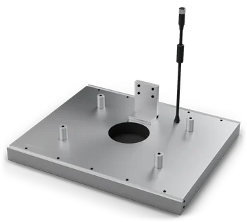 Ceres area lights
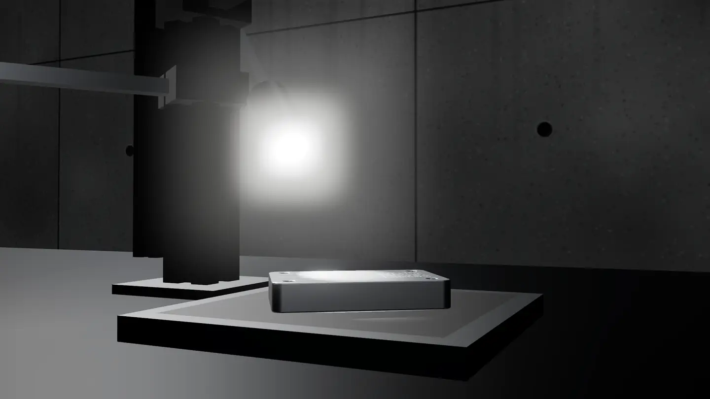
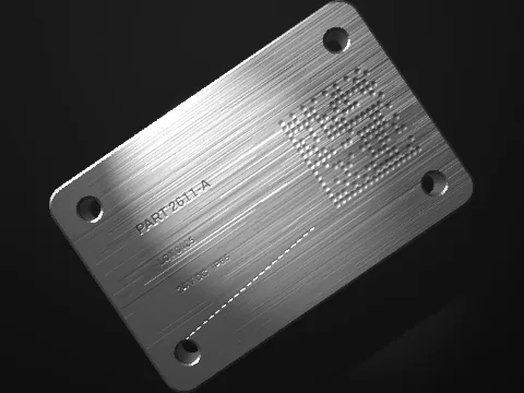
Spot light
A focused beam puts high intensity on one small area.
Use it forSingle features, long working distances, extra light on one part of a scene.
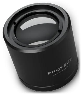 Stellar spot lights
Choosing the colour of the light
Most inspection cameras are monochrome: they record brightness, not colour. The colour of the light then decides which features look bright and which look dark.
Same colour, lighter
A coloured feature lit in its own colour reflects strongly and looks light. Red ink under red light almost disappears.
Opposite colour, darker
Lit in the opposite colour, the same feature absorbs the light and looks dark. Red ink under green or blue light turns dark.
- Ultraviolet makes fluorescent materials glow, which shows adhesives, coatings and lubricants that contain a fluorescent tracer.
- Blue has a shorter wavelength, which can resolve finer detail, sharpen backlit edges and bring out surface features.
- Red is a common default with monochrome cameras. With a band-pass filter on the lens matched to the LEDs, it also blocks most room light.
- Infrared passes through many dyes and inks that are visible to the eye, so carbon-based black print can be read through coloured overprint. It is also less affected by colour differences between parts.
White suits colour cameras, and inspections where the colour itself is the feature.
Proteus lights come in white, red, green and blue, with infrared and ultraviolet in the Saturn range and on custom designs. See colour filtering with coloured light for a worked example.
Polarisation
Polarisers reduce glare. Place one polariser in front of the light and another on the lens, turned 90 degrees to it: this is cross-polarisation. Light reflected directly off a glossy surface keeps its polarisation and is blocked at the lens. Light scattered by the matte detail underneath loses its polarisation, and part of it gets through. The result is the detail without the glare.
Polarisers absorb a large share of the light, so allow for more intensity or a longer exposure.
Saturn ring lights take a polariser as an option.Distance, size and evenness
Light falls off with distance: moving a light back covers more area, at lower intensity.
A light should be larger than the area it has to light evenly. A small source makes a bright centre and dark edges.
Check evenness with a flat grey card in place of the part: capture an image, then compare the brightness at the centre and in the corners.
Fix the geometry mechanically. A light that moves a few millimetres changes the image as much as a different part would.
Strobing and exposure
On moving lines, a short exposure freezes the motion. Strobing switches the light on only while the camera exposes, triggered by the same signal. The light can then be bright for a short moment, the LEDs run cooler than at the same brightness continuously, and room light contributes less to the image.
Saturn ring lights take a strobe input from 5 to 24 V, with 1 to 5 V as an option.
Room light
Daylight and factory lighting change through the day and add reflections of their own.
- Shield the inspection area.
- Use a single-colour light with a matching band-pass filter on the lens.
- Keep exposures short so the inspection light dominates.
What to tell us when you need a light
Four facts are enough for a first recommendation:
The part material, finish and size.
The defect or feature you need to find.
The working distance from the light to the part.
The camera and lens.
Line speed, mounting space and the environment help us refine it. Send them to an engineer, who replies with the light, or designs one.
Common questions
What is the best light for shiny parts?
It depends on the shape. For flat shiny faces, use a co-axial light. For curved or uneven shiny parts, use a dome light. To find raised or recessed features on flat metal, use dark field with a low-angle ring light.
What is the difference between bright field and dark field?
In bright field, a flat surface reflects the light into the lens and looks bright, so marks look dark. In dark field, the light arrives at a low angle and the flat surface reflects it away, so the background looks dark and edges and marks look bright.
Which colour of light should I use?
With a monochrome camera, light in the same colour as a feature you want to hide, or the opposite colour to make it dark. Red is a common default; blue helps with fine detail; infrared reads black print through coloured overprint; ultraviolet shows fluorescent materials.
Do I need a backlight or a front light?
If what you need is in the outline, such as size, shape, position or holes, use a backlight. If it is on the surface, such as print, scratches or colour, use a front light.
Can you make a light to fit my machine?
Yes. We design custom geometries, sizes up to 2000 mm, wavelengths and polarisation. See custom lighting.